Research on LTE-A MIMO Application Scenarios and Application Status
“The development of antenna technology and signal processing technology has also made more and more people realize that increasing the transmission rate through multi-antenna technology is an effective way. MIMO (mutiple input mutiple output, multiple input multiple output) technology emerged at the historic moment. It uses space-time coding (STC) and uses multiple antenna arrays to achieve spatial diversity, multiplexing, or beamforming. Improved spectrum efficiency. Therefore, MIMO has become one of the essential key technologies for Wimax, LTE, 802.11n and almost all future “hot” wireless communication systems.
“
1 Overview
The development of antenna technology and signal processing technology has also made more and more people realize that increasing the transmission rate through multi-antenna technology is an effective way. MIMO (mutiple input mutiple output, multiple input multiple output) technology emerged at the historic moment. It uses space-time coding (STC) and uses multiple antenna arrays to achieve spatial diversity, multiplexing, or beamforming. Improved spectrum efficiency. Therefore, MIMO has become one of the essential key technologies for Wimax, LTE, 802.11n and almost all future “hot” wireless communication systems.
The LTE defined in the 3GPP Release 8 version uses MIMO technology, and its downlink peak rate can reach up to 300 Mbp (4×4 MIMO) and 150 Mbps (2×2 MIMO). In order to maintain the technical advantages and market competitive advantages of the 3GPP standard, 3GPP officially started the research and formulation of the LTE evolution standard-LTE-Advanced (hereinafter referred to as LTE-A) in April 2008, using the uplink 4×4 MIMO and the downlink 8 ×8MIMO technology.
2 LTE-A MIMO application scenarios
Recalling Shannon’s theorem, the channel limit rate is related to the available bandwidth and signal-to-noise ratio. Under the condition of a certain bandwidth, there is only an idea of hitting the signal-to-noise ratio. That is to increase the speed by increasing the signal-to-noise ratio, but when the signal-to-noise ratio is increased to a certain level and then the signal-to-noise ratio is increased, the speed will increase, but the improvement is not obvious. If drawn as a curve, the trend is similar to a logarithmic curve. .
C = BLOG2 + (1+ S/N) (1)
It can be seen that when the signal-to-noise ratio is very poor, the speed can be significantly increased by increasing the signal-to-noise ratio. Therefore, the application of transmission diversity and beamforming technology can effectively increase the signal-to-noise ratio of the received signal, thereby increasing the transmission rate and coverage. When the signal-to-noise ratio is already good, it is not obvious to increase the speed by increasing the signal-to-noise ratio. This is why even though the cost is high, operators will let the MIMO space division multiplexing mode debut. That is, in reality, the only way to increase the rate significantly under the condition of a good signal-to-noise ratio is to increase the rate through the new dimension of space. That is to say, it is suitable for MIMO space division under the condition of not far from the base station signal. Multiplexing mode. In the case of the edge or poor coverage of the base station, it is more suitable to use beamforming to improve the signal-to-noise ratio. Let’s take a look at the classification and application scenarios of LTE-A MIMO technology in detail.
2.1 Space division multiplexing
Wireless signals are frequently reflected in dense urban areas, indoor coverage, and other environments, making the fading characteristics between multiple spatial channels more independent, thereby making the effect of space division multiplexing more obvious. Wireless signals have few multipath components in suburban and rural areas, and the correlation between spatial channels is relatively large, so the effect of space division multiplexing is much worse.
In reality, the deployment of MIMO communication networks can also be enlightened from the above analysis: in a typical cellular network, base stations are often set up in high places with wide open sides and few reflectors and obstructions. Therefore, in order to ensure MIMO The system enjoys better performance. Usually, the distance between antennas should be increased on the base station side (at least 5-10 times the wavelength) to ensure enough uncorrelated multipath signals; the situation on the user side is different. There are a lot of buildings and walls around us, and users themselves are surrounded by natural and abundant reflectors. Therefore, user equipment generally does not need too large antenna spacing to meet performance requirements (usually 0.5~ of the wavelength). 1 times), now there is no need to worry about future mobile phones with antennas that diverge like horns.
For MIMO applications suitable for dense urban areas, two MIMO modes, open-loop MIMO and closed-loop MIMO, can be selected, as shown in the figure. 1 Among them, closed-loop MIMO has higher environmental requirements because the base station relies on the feedback information of the terminal for precoding, but due to the feedback adjustment of PMI/RI, its data reliability is relatively strong; for open-loop MIMO, its robustness is relatively strong, SNR requirements and channel correlation requirements are not as strict as closed-loop MIMO.

Figure 1 Two implementation forms of MIMO space division multiplexing: open loop and closed loop
2.2 Beamforming
Beamforming, also called beamforming or smart antenna, has been widely used in 3G technology. By performing phase weighting on the correlation of the output signals of multiple antennas, the signals form in-phase superposition in one direction and phase cancellation in other directions, thereby realizing signal gain. When the system transmitter can obtain channel state information (such as TDD systems), the system will adjust the phase of each antenna’s transmit signal (data is the same) according to the channel state to ensure the maximum gain in the target direction; when the system transmitter does not know the channel In the state, random beamforming can be used to achieve multi-user diversity.
When beamforming technology can obtain channel state information, it can achieve better signal gain and interference suppression to improve cell edge performance. The beamforming technology is not suitable for dense urban areas, indoor coverage and other environments. Due to reflections, the receiving end will receive too many paths of signals, resulting in poor phase superposition.

Figure 2 Schematic diagram of the beamforming antenna array principle
In reality, the TDD-LTE uplink and downlink used by China Mobile use the same frequency, so the uplink and downlink channel conditions can be obtained through unilateral channel estimation. Therefore, the TDD network is very suitable for beamforming (because of the beamforming function The premise is to have a good estimate of the channel), can improve a certain signal-to-noise ratio, and have stronger coverage at the edge of the network. The FDD-LTE uplink and downlink are different frequency bands, so it does not have this advantage, and beamforming is generally not used.
2.3 Dual-stream beamforming = beamforming + space division multiplexing
Whether beamforming (smart antenna) can achieve significant gain is affected by the wireless environment. The wireless environment can be divided into the following two types:
1) The line of sight (LOS) has a poor scattering environment, which is more conducive to the use of smart antennas: high correlation between antenna elements, obvious main path, concentrated energy, simple shaping algorithm, and affected by channel estimation accuracy Small, the smart antenna is easy to gain gain.
2) The non-direct line of sight (NLOS, none line of sight) has a rich scattering environment, and it is difficult for smart antennas to obtain obvious gains: the antenna array element has low correlation, the main path is not obvious, the energy is scattered, and the shaping algorithm is more complicated. The estimation accuracy has a large impact, and it is more suitable to use MIMO spatial multiplexing.

Figure 3 Principle of dual-stream beamforming antenna array
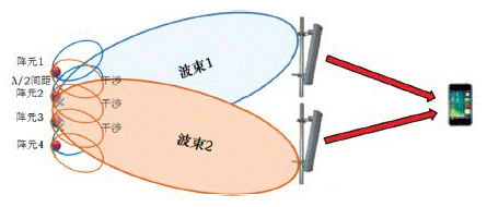
In order to coordinate the contradiction between beamforming and space division multiplexing, dual-stream beamforming is a scheme that combines beamforming and space division multiplexing to maximize strengths and avoid weaknesses. It superimposes two sets of shaping weights on a pair of antenna elements to form two beams. From the perspective of the terminal, two equivalent “virtual antennas” are formed. On the two virtual antennas, one user terminal can transmit different data, that is, space division multiplexing; it can also transmit data to two different user terminals, that is, space division multiple access.
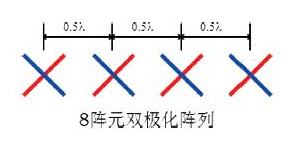
In order to achieve dual-stream beamforming, China Mobile’s TDD-LTE base station generally has 8 antennas, as shown in the red dashed box in the figure below. In order to achieve dual-stream beamforming, 8 antennas are divided into two groups.
● The polarization between the two groups of antennas is vertical cross polarization: the red group antenna +45° polarization, and the blue group antenna -45° polarization. In this way, the antenna correlation between the groups is low, so that the space division multiplexing can be easily realized.
● In each group of antennas, the antennas are spaced apart by about a quarter wavelength. In this way, the antenna array can achieve a high degree of correlation within the group, thereby making it easy to achieve beamforming.

Figure 4 TDD-LTE eight-antenna beamforming antenna array principle (top) and physical object (bottom)
3 Application status of MIMO in LTE
The LTE duplex mode adopted by the three major operators is different, and China Mobile has decided to adopt TDD-LTE. In the large-scale field test, the boundary conditions of the wireless communication environment are complicated, and it is particularly important to use different transmission technologies to adapt to different application scenarios. If you choose improperly, you will not only fail to achieve the optimal network performance, but will also cause adverse effects such as increased network interference. Several modes of MIMO are suitable for different scenarios. They are divided according to the boundary conditions of handover. From the center of the city to the suburbs and the edge of the cell, the following transmission methods can be used to deploy the network: closer to the base station, strong signal, and close to the city. Centers and urban centers with strong multipath fading can use closed-loop MIMO. Due to the closed-loop RI/PMI feedback, the rate is stable, the bit error rate is low, and multi-antenna gain can be obtained, but the boundary conditions are stricter; If the environment is poor, the SNR is low, and the channel correlation is slightly lower, you can use the open-loop MIMO method; in the suburban areas of the city, which are relatively open and have high channel correlation, choose beamforming and beamforming according to different speeds. The technology can also take advantage of the reciprocity of the uplink/downlink channels in the TDLTE system to dynamically perform beamforming for a single user, thereby effectively increasing the transmission rate and enhancing the coverage performance of the cell edge. All of the above modes can be switched to transmit diversity mode. The transmit diversity mode is robust and has low requirements for speed, channel environment and SNR, but it cannot generate multi-antenna rate gain. You can only enjoy the multi-antenna parallel transmission. The diversity gain.
If the operator uses FDD-LTE, according to the above, more will use 4×4 or 8×8 MIMO space division multiplexing.

Figure 5 The theoretically best MIMO application scenario for TDD-LTE cells
The Links: BSM300GA120DN2 PM100RSD120


